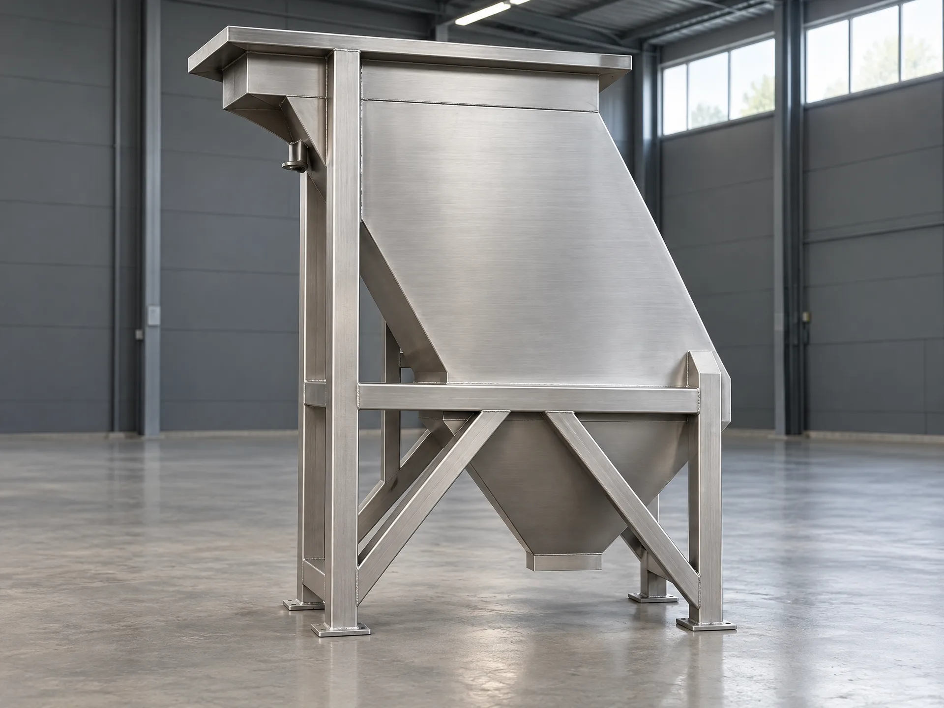
Plate Settler Design Calculation
The Complete Design Workflow
A full design calculation goes beyond area and plate count to include sludge handling, hydraulic distribution, materials and safety factors.
Plate Settler Design Calculation
A robust design calculation follows a defined sequence: characterise the influent, set the effluent target, establish design flow, select loading rate, compute area and plate count, then size sludge handling and hydraulics.
Solids mass balance is essential — the mass of solids captured per day drives hopper volume, desludge frequency and pump sizing. Ignoring it leads to sludge encroaching on the plates.
Material selection (SS 304 or 316L), plate spacing and inlet/outlet design are finalised against the specific water chemistry. A safety factor of 1.2–1.5 is applied to absorb variability.
A = (Q × SF) / SLRDesign area including safety factor.
M_solids = Q × (TSS_in − TSS_out)Daily captured solids mass, driving sludge system sizing.
Design Inputs
Free Sizing Check
Try the interactive Plate Settler Sizing Calculator, or send us your flow and water-quality data for a preliminary sizing at no cost.
Key Considerations
Solids Balance
Size the sludge system to captured solids mass, not just the plate area.
Hydraulics
Verify even distribution and weir loading at peak flow.
Materials
Match stainless grade to chlorides and water chemistry.
Request an Engineering Assessment
Our engineers will review your application, flow rates, and water quality data to recommend the optimal plate settler configuration.